
FAQ
Wi-Fi problem cure master
Frequently Asked Questions and Answers:
Q1. What is Wi-Fi problem cure master ?
The Wi-Fi problem cure master
It is a RF revolution for fixing all problems of existing WiFi !!
It is a new platform basing on “NON-LOS”, “Interference-Free”,”Multi-hop” and “IP management and aggregate”, while “customization on project base” as adding vantage. The core expertise drives from LTE(4G) network + 600MHz TDMA with proprietary IC and firmware design aiming at supporting all most challenging applications and locations like mining, marine, city street surveillance, police surveillance system, bus route line feed, POS (LTE backhaul + UHF last mile), portable MESH system for fast deployment for disaster site (firing, flooding, quake…), telemetry, border patrol…..etc
With "NON-LOS", "Interference-Free", "Multi-hops" and "IP management and Aggregate", it will fix all incurable problems of existing traditional WiFi technology, as a WIFI PROBLEM CURE MASTER for all kind of WiFi problems (such as LOS, interference, limited coverage…) that suffered by Wi-Fi users.
(▲TOP)
Q2. Factors that may possibly affect RF transmission range?
Possible factors are:
- Geographical factors: high building, hill, mountain, or even a big group of birds, strong power field all will affect (block) the RF transmission. This is the main factor.
- Interference (magnetic noise and RF clash): Changing RF channel may improve it. RF channel plan is crucial.
- Climate factors: Humidity (rainy) and salty (sea shore) will also affect (block) the RF transmission.
- Installation Workmanship: This factor causes poor RF transmission easily
- Antenna alignment could be the biggest reason accounts for poor RF transmission; please contact us for detailed procedure for antenna alignment.
- Antennas, cables, connectors are somehow damaged during the installation process.
- Device failure or inadequate functionality:
- As above-mentioned, relating devices are damaged during the installation process;
- Antenna gain is not enough, or antenna cable is too long.
(▲TOP)
Q3. Higher or lower frequency can go farther?
It is a very frequently asked question by people, but normally not easy to get a proper answer on it. Let’s say it this way, with the same output RF power, the coverage of higher frequency and lower frequency are not much different from each other. However, higher frequency is much easier to be blocked by geographical conditions, such as hill, high building, and sometimes even by a big tree, in another word, lower frequency is easier to “bypass” the blocking objects; hence in turn results in the common reality that radio band with lower frequency reach farther distance than the one with higher frequency does.
(▲TOP)
Q4: KB vs. Kb?
It depends on the venue to use it. Firstly, let’s review the relation between them; we know that ‘bit’ is the basic unit of data. 8 bits make one Byte (1 Byte = 8 bit).
Normally, when calculating a size of a file, we use KB (byte) while Kb (bit) for transmission speed. With knowing this, when transmission speed is mentioned, it is referred this way:
9600bps: 9600 bits per second; or
14.4Kbps: 14400 bits per second; or
56Kbps: 56000 bits per second; or
512Kbps (ADSL speed): 512000 bits per second; or 64KB (Bytes) per second.
1Mbps, 1 megabit per second;
40Mbps, 40 megabit per second….etc.
Therefore when referring to WLAN transmission speed, if KB is used, we need to times 8 to be Kb; e.g. 800KBps = 6.4Mbps (6400Kbps); 2MBps = 16Mbps….and so on.
(▲TOP)
Q5. ideal length for antenna cable?
Length of antenna cable is one of the major factor affecting the RF performance.
Length will attenuate the antenna gain and that’s the reason for making outdoor unit; to keep the cable to the least. The cable in our standard pack has been tested with most ideal length, 30cm~1.5m, please do not change it.
Length will attenuate the antenna gain and that’s the reason for making outdoor unit; to keep the cable to the least. The cable in our standard pack has been tested with most ideal length, 30cm~1.5m, please do not change it.
(▲TOP)
Q6: Factors affecting WLAN connecting distance:
There are some 6 factors affecting the connecting distance;
- Cabling: cable quality and installation workmanship are crucial, cable should not be jointed for extending the cable length.
- Water goes in Connector or Lightening Protector: Waterproof must be done very well to the connector and lightening protector.
- Geographical blocking: Line of sight (LOS) is very critical for 2.4GHz and above;
- Antenna alignment' does affect greatly the transmission distance.
- Antenna Gain: If the connecting distance is still not satisfied, then you may consider using a higher gain antenna,
- RF Power: if the result is still not satisfied after using a higher-gain antenna, then bigger RF power may be the solution.
(▲TOP)
Q7. Antenna usage: Omni-antenna vs. antenna splitter?
When covering a 360-degree range, there are two ways to achieve it:
- Install 4 antennas, each for a sector (90 degree), and using an antenna splitter (4-way) to accommodate the antennas simultaneously; the benefit is that we can use higher gain antenna for this scenario while the set-back is that the splitter will reduce the antenna gain (insertion loss);
- Use an omni-directional antenna; the advantage is that there is no gain loss while the omni-antenna gain is usually relatively lower;
(▲TOP)
Q8. Reasons for unstable connection? Why RF connection is sometimes very bad and sometimes extremely good?
Interference could be the main reason, please check follows,
1)Electron magnetic wave interference; please check the environment of the site where the device is installed, is it in a factory? or a factory with big machine near by it? or any big power field source nearby?
2)is the antenna alignment optimized?
3)is the problem only happening when certain machine is in operation?
If the answer is yes, then situation becomes clear and simple now,
1>keep the WiFi radio as farther as possible (height is helping greatly) from the machines.... it is a very common phenomenon that RF is very easily interfered by 'electromagnetic wave': big power field, motor, big machines; all are killers for RF;
2>check if the electricity power source is "NOT clean"; has the RF unit or PC shared the power with the machines? Please do make the power source is 'clean' for the RF unit; Separate the power source if they are sharing the same power source area. Definition
for same power source is:
A>the same circuit loop (same fuse);
B>same control box;
Remedy to power interference: give an independent power source for the RF unit by connecting new power wire from the 'most outer' (or the most origin) in the 'inlet' of power cord from public loop. Make such power cable bypass other loop may share with the machines. If it is too troublesome, then a 'power filter' is required.
(▲TOP)
9. LOS vs. non-LOS (line of sight)
Line of Sight (LOS) is a factor for all RF connection, and is 'crucial' (but not essential) for wireless LAN. But is non-LOS possible? It is possible and there is always non-LOS connectivity but only a matter of 'range', even a small USB dongle is always connected in a building without LOS, but again only a matter of range. Nevertheless, those WLAN products claiming non-LOS capability over dozens of kilometer is extremely irresponsible !!
It is a nature physical phenomenon, and distance and frequency are major factors. Only low frequency has no LOS issue due to its long wave length, like FM, AM, TV, and walky-talky; the lower frequency the farther distance it can reach; but lower frequency contain less info (bandwidth)..........For example, the US or USSR, when their nuclear sub-marines need to communicate with their HQ over thousand miles away, they are using 'super low' frequency to send only 'telegram code', but it can go super far due to the super low frequency (huge long wave length).
If you want high speed, to have a large number of data; then you will need higher frequency, above 2.4GHz; and then high frequency is very easy to be blocked due to its short wave length......as below-listed drawing for your info;
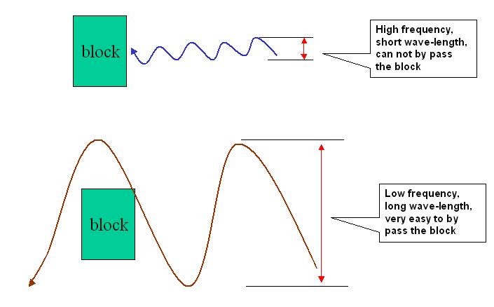
that's why LOS is an issue for all high data speed solution basing on high frequency (above 2.2GHz) like WiFi, WIMAX, Micro wave, PDH, (that's why WIMAX is boasted off too much.......)
(▲TOP)
Q10. Operating mode: AP-Client vs. Bridge mode, which one is better?
It depends on the purpose of the deployment. For a typical LAN expansion application link backhaul PtP or PtMP. Surely Bridge mode is recommended !! AP-client mode is under a 'broadcast' scenario, the AP is always scanning if there are new clients to add-in and serve, and then others CPE will same keep requesting if it can be associated; hence AP will always under a mode to seeking and say 'NO' (reject).... it is an additional burden for the AP and also a disturbance to the existing connection.
When it is under bridge mode, it is a dedicated line, both units (master and slave) only look at each other (by MAC address).
Below-listed for your further info:
Bridge mode: it is a dedicated link mode, only connect the assigned point or points. The master and slave only look at each other (by MAC address). Unlike AP/CPE, it is subject to proprietary protocol, and most suitable for doing a 'backhaul' -- a dedicated line;
AP (access point): as the name given, it is the point to 'access' the network, it is under broadcasting scenario with universal WiFi protocol. It broadcasts the signal to all clients as last mile service and ready to serve them any time when conditions are matched (SSID, encryption....).
Client or CPE (client premise equipment): used by the client like a laptop or USB; or outdoor CPE mounted on roof to associate with the AP, and then the computer connect the CPE by LAN cable.
(▲TOP)
Q11. What is dusk-to-dawn street lamp mode?
Solar Charge Controller with Automatic “Dusk to Dawn” control for street lights and eliminates expensive photocell /relay needs and installation.
Our SC series (Solar Charge Controller) now have the design of street-light mode.
So while this is a Solar Charger with a primary function of charging, our SC series also will provide a control- on/off DC load for any DC device. This was developed from our market research that most DC device used in solar projects are lighting device such as street lights, security devices and display signs for road warning or advertising. Our R&D designed a selection of “ street-light mode “.
When selected ,during the day-time, in order to save energy, the DC connected load will stop output voltage to the lighting devices. But at night-time or Darkness , the controller will start a output to the lighting device. Now this new feature eliminates expensive relays and photocells installation in many applications , we accomplish this by detecting the voltage output of the solar module and our microprocessor controlled controller energizes the output terminals shown above on the device. With the ever evolving solar charge controller industry we are very interested to develop application markets .If you have a special request other than a lighting load , please let us know so that we can research an application and provide a model application by modifying our software for the microprocessor controlled Controller.
(▲TOP)
Q12. What is solar hybrid system?
It is dual input source from solar & AC-line. with additional AC-in option (hybrid input: solar and AC-in). The solar inverter has additional AC-in. When battery power becomes too low, the inverter will automatically switch to AC power source for operation (auto transfer) (charging is still performed by solar panel). Switching scenario as follows:
Inverter switch to AC line : <11.2V ± 0.5V(12V); <22.4V ± 1V(24V)
AC line switch to Inverter : >13.2V ± 0.5V(12V); >26.4V ± 1V(24V)
Inverter switch to AC line : <11.2V ± 0.5V(12V); <22.4V ± 1V(24V)
AC line switch to Inverter : >13.2V ± 0.5V(12V); >26.4V ± 1V(24V)
(▲TOP)
Q13. What does MPPT stand for solar charging ?
MPPT stands for "Maximum Power Point Track". It is for is for solar charge controller, seeking for max. charging efficiency; which is a technique that solar inverter use to get the max. possible power from the PV array. A tangible practice is like this, as the sun shine will not always at the same level, sometimes stronger, sometimes weaker; so when sunshine is stronger, the MPPT charge controller will automatically adjust the voltage lower (so make current-amp higher) for more amperage charged into the battery; and then when the sunshine is weaker, the controller will adjust the voltage higher to keep the charge going, and thus keep the max. possible charging time and max. possible charging.
(▲TOP)
Q14. will fast charging harm batteries?
Yes, It would, and definitely would if it is a cheap crappy, or traditional and normal charger with no “brain”.
Most people has the concern over high rapid charger, would it be harming the battery? YES, It will definitely harm the battery if the battery charger is a cheap crappy, or traditional and normal charger with NO “brain” !!
Our AD series is different, our chargers are micro-processor controlled Intelligent charger and inverter, it is designed with high capacity for "rapid" charging while no harming the battery. It supports 4 charging stages: soft start, bulk charge, slow charge and finally ‘float charge’, the charging will be slow-fast-full speed- then maintaining charge to keep the amperage while protecting the battery. It will automatically reduce charge amps and voltage based on voltage conditions (as battery is charged, the voltage will vary from 11.xx volt and up and up 12v, 13v… until it is fully charged), and our ‘intelligent’ charger will reduce automatically the charging speed (less amp and lower voltage) until it is fully charged. So as the microprocessor chargers we have a selection of battery type and all is automatic. Batteries are secured while charging is fast and highly efficient.
(▲TOP)
Q15. Antenna type
Generally, there are 6 common type of antenna:
For performance wise, there are two major factors, beam-width & antenna gain.
As a common rule, the broader the beam-width the lower the antenna gain, accordingly the shorter distance range but wider coverage.
The smaller the beam-width, the higher the antenna gain, accordingly the farther the distance range while narrower coverage;
So omni-directional and sector antenna are mostly for broadcasting (point to multi-point). While others are for point-to-point connection, and the selection of antenna type is based on distance to reach.
Bear in mind that higher gain antenna with narrower beam-width is more difficult to make connection, thus requires higher antenna alignment skill and experience.
| Type | Application |
Beam width (Relatively)
|
Range Attainability (1 to 10; Relatively)
|
| Omni-directional |
PtMP Broadcast
|
Omni-directional Broadest, 360 degree
|
Width : 10 Distance: 1
|
| Sector Antenna |
PtMP Broadcast
|
90 ~ 120-degree |
Width : 7~8 Distance : 3
|
| panel |
PtP backhaul
|
20 ~ 45 degree |
Width : 5~6 Distance: 5
|
| yagi |
PtP backhaul
|
9 ~ 15 degree |
Width : 3~4 Distance : 6~7
|
| Parabolic Grid |
PtP backhaul
|
6 ~ 9 degree |
Width : 2 Distance : 8~9
|
| Dish |
PtP backhaul
|
3 ~ 5 degree |
Width : 1 Distance : 10
|